Make changes in the ground reviewable.
An open-cast mine has two related but distinct measurement tasks: calculating changes in surveyed surfaces and observing movement over time. Long-range terrestrial LiDAR can support repeat surfaces, sections and volume calculations. Radar, total stations, GNSS control checks and local geotechnical instruments add different observations. A shared workspace should connect these tasks without confusing quantities with displacement or a safety decision.
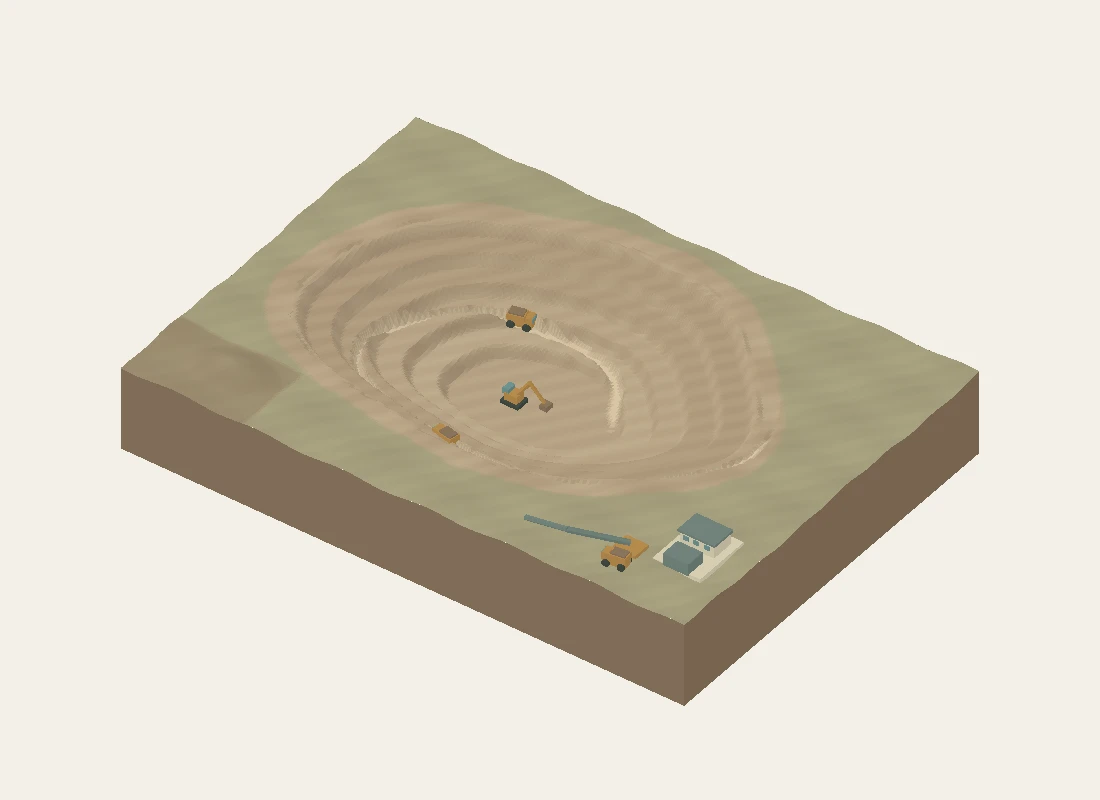
Explore the same site in the interactive experience.
Create comparable survey surfaces
Plan scan stations, control and coverage around benches, working faces and stockpiles. Register survey epochs to a checked reference, define the comparison boundary and review filtering and coverage before calculating changes. The conceptual scanning animation does not replace a real visibility or occlusion assessment.
Calculate and qualify quantities
Compare consistent surfaces and distinguish excavation from addition. A stockpile inventory also needs an agreed base surface. Terrain height-surface methods do not represent every overhang or cavity. Converting volume into mass requires material density and state assumptions; cut and fill in independent areas are not automatically a material balance.
Review monitoring components separately
Radar reports relative line-of-sight movement for a selected patch. A prism has point coordinates; a displayed displacement magnitude discards direction. An extensometer follows its installed axis. GNSS check residuals describe reference checks and measurement scatter, not proven monument movement. Review reference stability, quality and uncertainty before interpreting a trend.
Inputs to agree
- Survey control, epoch dates, comparison boundary and required uncertainty
- Scan coverage, filtering rules and stockpile base definition
- Monitoring geometry, reference points and instrument-quality information
- Agreed report definitions, review responsibilities and site monitoring procedures
Possible outputs
- Registered repeat-survey surfaces, sections and contours
- Cut/fill and stockpile quantity reports with a stated method
- Distinct radar, prism, reference-check and local movement histories
- Spatial review combining quantities with monitoring context
Keep the measurements distinct
| Quantity | Unit or component | Interpretation |
|---|---|---|
| Radar displacement | Relative line-of-sight component | Depends on viewing geometry and a defined reference. |
| Prism displacement magnitude | Magnitude of a 3D point-coordinate change | Discards direction; needs reference and uncertainty checks. |
| Extensometer movement | Change along the installation axis | Local extension between the defined anchors/reference. |
| GNSS check residual | Difference from an adopted control value | Includes solution scatter; not proof of monument movement. |
Why can radar, prism and extensometer displacement values differ?
They may observe different locations, axes and reference times. Radar sees the component along its line of sight; a prism provides a point-coordinate solution; an extensometer measures local extension along its installation. Different values are not necessarily contradictory, but they cannot be compared as if they measured one identical movement vector.
Do small residuals or a smooth displacement trend mean a highwall is safe?
No. A stability interpretation needs an appropriate monitoring programme, reference and data-quality checks, geological and operating context, and site-specific review and response procedures. The illustrative site contains no universal movement threshold, alarm service or failure forecast.
Technical references
- Australian Centre for Geomechanics: slope-radar geometry and interpretation
- Caterpillar: representative haul-road design considerations
Further reading on the measurement principles discussed above.
Content reviewed · Skyrover